High-Precision Aircraft Engine Display Model Manufacturing Process
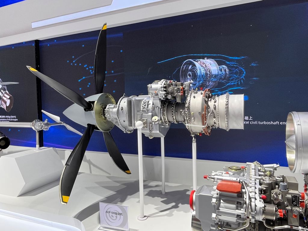
I. Core Component Forming Process
Fan Module Construction
Titanium alloy blades are precision cast using the lost wax method, and each blade is individually aerodynamically shaped.
The rotor disc is processed using five-axis联动加工, and the tenon and groove areas retain the original tool marks.
The inlet duct is spun-formed using transparent PC material, and the inner wall is etched with anti-icing piping.
Combustion Chamber Components
The flame tube is laser-cut from 316L stainless steel and manually rolled into a cylinder
The fuel nozzle array is processed using micro-hole EDM
The double-wall structure is vacuum brazed
2. Material Selection Scheme
High-temperature section components: nickel-based alloy 3D printing + hot isostatic pressing
Piping system: Annealed copper tubing followed by cold working hardening
Casing structure: Carbon fiber prepreg molded
Fasteners: 12.9-grade alloy steel bolts scaled down to actual proportions
III. Surface Treatment System
Pre-treatment stage
Sandblasting: 80-grit glass beads applied to all metal components
Passivation treatment: Electrolytic polishing of stainless steel components
Primer coating: Epoxy zinc yellow primer + baked at 120°C
Functional coating
Compressor section: Gradient anodized treatment
Turbine section: High-temperature ceramic coating + thermochromic temperature-indicating paint
External piping: Color ring markings applied using laser transfer technology
4. Detail reinforcement process
Simulation of usage traces
Mineral oil residue accumulation at lubrication pipe interfaces
Aluminum oxide particle erosion effect sprayed on turbine blade leading edges
Hydraulic oil leakage traces retained on thrust reverser actuator cylinder
Dynamic display design
Magnetic levitation bearing supporting rotor system
Fiber optic light guide simulating combustion chamber flames


