Process of Model Making for Curved Surface Fitting Equipment
After the customer provides the drawings of the surface fitting equipment, the model production will revolve around the drawing data, and through material selection, sub component processing, precision assembly, surface treatment and other processes, the core structure and functional features of the equipment will be restored. The following are the key production steps:
1、 Drawing analysis and structural disassembly
Firstly, the technical team will perform dimensional annotation and in-depth analysis of the structural logic on the customer's drawings, clarifying the core components of the equipment
Imitation fixture mechanism: It is necessary to restore the "split type bearing skeleton+separated driving components" (as shown in the drawing, "the bearing skeleton is connected to the separated driving components, and the driving opens to both sides along the first direction");
Tensioning mechanism: It needs to be installed on both sides of the profiling fixture in the first direction, clamping and tensioning the load-bearing film;
Attach the copying mechanism: It is necessary to meet the requirement of "moving relative to the copying fixture in the first direction and attaching the load-bearing film to the copying surface";
Positioning fixture mechanism: It is necessary to achieve "relative contour surface movement, place the curved cover plate above the flexible screen body and fit it together".
2、 Materials and Parts Processing
According to the drawing structure, select suitable materials and process them into components:
Main structure: Made of ABS sheet metal (laser cut to form cabinet doors and frames), with a surface sandblasted to simulate a metallic frosted texture;
Detail components:
Hinges: micro brass parts hand riveted to ensure smooth opening and closing of cabinet doors;
Hanging ring: made of 3mm diameter stainless steel wire bent, welded with metal inserts, with a load-bearing test of ≥ 5kg;
Operation panel: CNC carved display screen groove (0.2mm deep), filled with gray acrylic board to simulate the screen; The button adopts dual color injection molding (black ABS base+colored soft rubber button); The interface is stamped with metal foil and the edges are polished smooth.
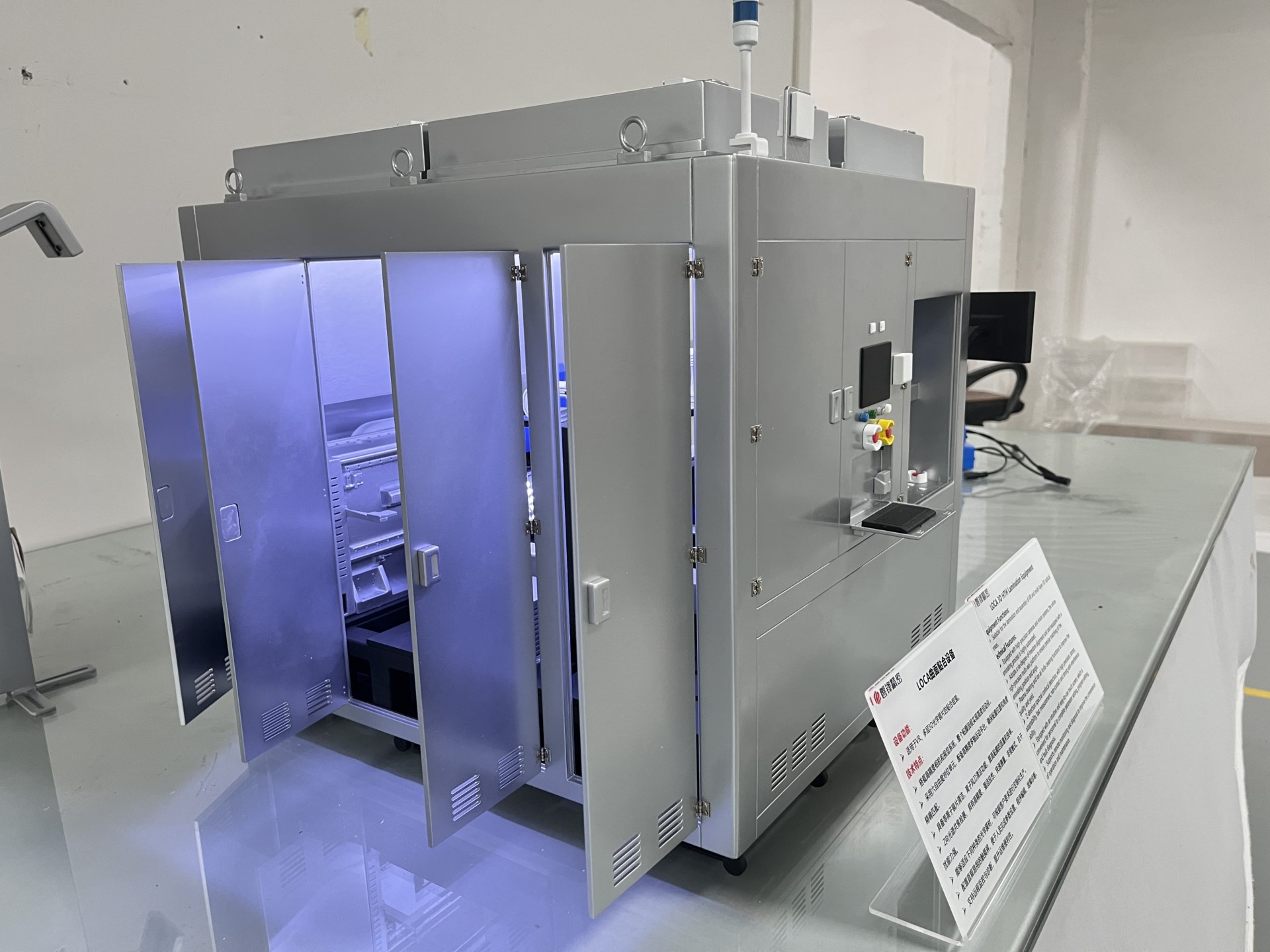
3、 Precision assembly and functional restoration
Realize precise component docking through "modular splicing", with a focus on restoring core functions:
Internal framework: First fix the internal framework, then install the cabinet door, operation panel, and top components in sequence, with seam gaps controlled within 0.3mm;
Backlight system: laser engraved grooves on acrylic board, blue semi transparent PET film pasted on the inside, embedded with micro LED light strips (battery box hidden at the bottom of the cabinet, wires hidden in the interlayer, switch controls backlight lighting);
Detail enhancement: Paste a 0.5mm thick black sponge strip on the edge of the cabinet door to ensure a tight fit when closed; The display screen logo adopts UV printing technology, and the font size is consistent with the original drawing.
4、 Surface treatment and texture restoration
Realize silver gray metallic texture through the "three-step spraying method":
Primer: Grey epoxy primer (thickness 20 μ m), dry and wet grind with 600 grit sandpaper to remove particles;
Topcoat: Silver gray metallic paint is sprayed in 3 thin coats, with a 15 minute interval between each coat, to avoid sagging;
Protective coating: Transparent matte varnish finish, weakened reflection to match the industrial texture of the original equipment;
Detail optimization: Use fine sandpaper to lightly sweep the edges and corners, manually create "usage marks", and then spray nano protective coating to enhance wear resistance.
5、 Detail debugging and quality verification
Backlight system: LED light strips are embedded along the inside of the observation window, wires are hidden in the cabinet compartment, and the switch controls the backlight to continuously and stably light up;
Identification matching: The top white detection probe is formed by turning ABS rod, and the blue identification adopts UV printing technology, with font size consistent with the drawing;
Final verification: Use a vernier caliper to measure key dimensions, with an error controlled within ± 0.5mm; Manually test the opening and closing of the cabinet door 50 times to ensure that the hinges are not loose and the backlight system is continuously and stably lit.


