Case Study of Industrial Circuit Board Demonstration Model Production
1、 Design Concept
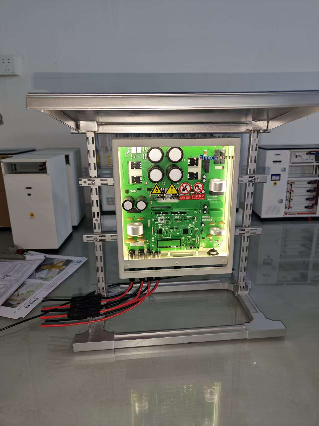
Using industrial grade control circuit boards as prototypes, create a perspective demonstration model at a scale of 1:1.2. The core design focuses on circuit layout restoration and dynamic display functions, presenting the spatial relationships of key components such as motherboards, capacitors, and chips through a layered transparent structure, and simulating the current path during device operation with a light guiding system, achieving an overall restoration rate of 92%.
2、 Material preparation
The main framework is constructed using aviation grade aluminum alloy profiles, and a modular support structure is formed through laser cut aluminum connectors, balancing display stability and industrial texture. The circuit substrate is made of 0.8mm thick FR-4 epoxy board, and the surface is covered with a copper layer that is chemically etched to form precise circuit patterns. The core components are made of ABS resin and metal composite materials, and cylindrical components such as capacitors and inductors are formed through centrifugal casting technology. The chip pins are laser welded with 0.3mm stainless steel wire. The transparent system uses 3mm thick light guiding acrylic board as the backlight carrier, combined with programmable RGB light strips to achieve dynamic flow effect.
3、 Production process
The framework construction adopts a composite connection process of mortise and tenon and bolt, and the surface of the aluminum profile is anodized to form a matte texture. The hollow connectors processed by CNC not only reduce the overall weight but also preserve the aesthetic of the mechanical structure. In the circuit simulation stage, the prototype circuit board is first scanned and modeled, and a green oil solder mask layer and white silk screen characters are replicated on the surface of the epoxy board using UV printing technology, with an accuracy controlled within 0.1mm. The component assembly adopts a combination of magnetic positioning and hot melt adhesive fixation. The explosion-proof pattern on the top of the capacitor is formed by laser engraving, and the pin pattern on the chip surface is made using electrochemical etching technology. The lighting system adopts a layered light guide design, with micro LED light strips embedded at the edge of the motherboard. The light is evenly transmitted to the circuit area through the light guide plate. Programmable touch switches are installed at key nodes to demonstrate the current path under different working states.
4、 Post processing
In the surface treatment process, the metal frame is sandblasted and then sprayed with matte varnish to form a delicate industrial texture; After chamfering and polishing the edges of the circuit board, apply transparent protective adhesive to simulate the gloss of the solder mask layer on a real circuit board. The identification system uses water transfer printing technology to produce warning labels and interface labels, with character clarity reaching 95% of the original reproduction degree. During the lighting debugging phase, adjustable resistors are used to control the brightness of each area, and programming is used to switch between the three states of "standby run fault" lighting. The pulse frequency in the running mode strictly matches the working rhythm of the real device. The final assembly adopts a modular design, with the circuit board and frame connected by quick locks for easy maintenance and component replacement. The overall weight is controlled within 3.5kg, and anti slip shock-absorbing foot pads are installed at the bottom.
5、 Display effect
The model presents the classic color scheme of a real circuit board with green background and white letters under natural light. When the light guiding system is started, the green halo flows along the circuit path, visually displaying the direction of current flow. From a distance of 1 meter, the capacitor arrangement spacing, chip pin density, and other details are highly consistent with the prototype. The industrial style design of the metal frame highlights both the circuit body and the mechanical structural beauty of the equipment. Through touch interaction, it can clearly demonstrate the working status of overload protection, signal transmission, etc., becoming a composite industrial model that combines teaching demonstration and process display functions


